Living in a house full of music afficionados, the medium for listening to music changes regularly. There's a large collection of records, 7"s, singles, and cassette tapes. Not to mention we all listen to digital media pretty often as well.
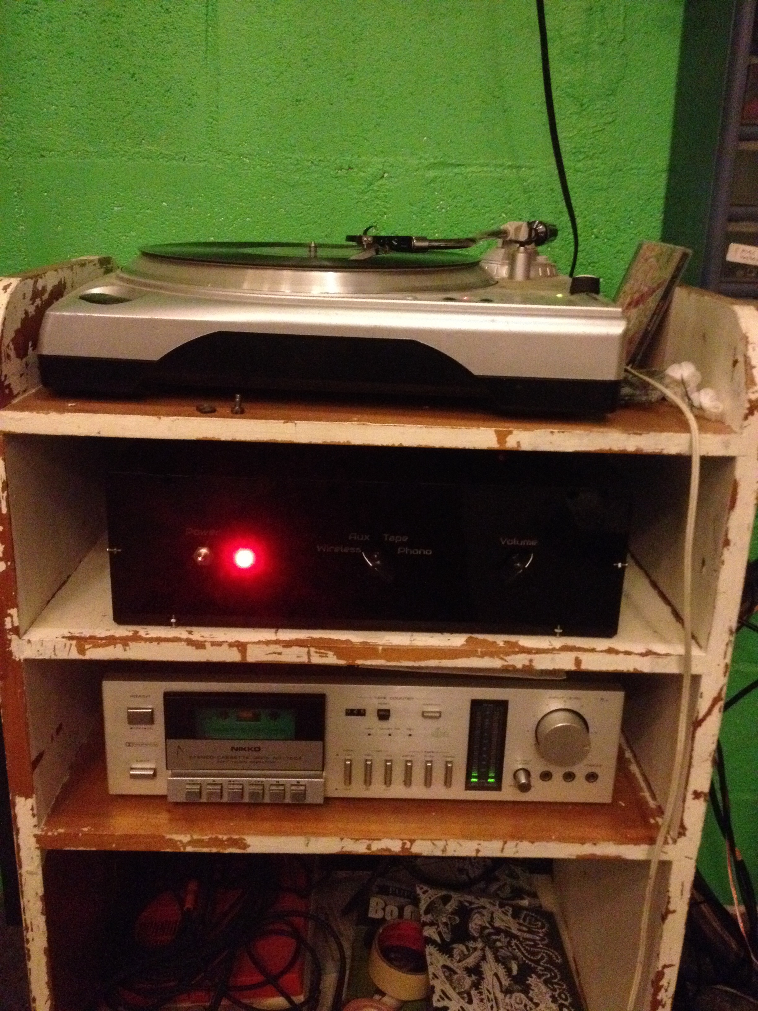
Because of this, the sound system in our living room had many different components. The record player was connected to a preamp before it was sent to the amplifier. There was a standalone switchbox that toggled between phono, tape, and auxiliary inputs. Lastly, the amplifier was a small 15-watt kit I purchased on Parts-Express that massively underpowered our 100-watt speakers. I decided it was time to build something better.
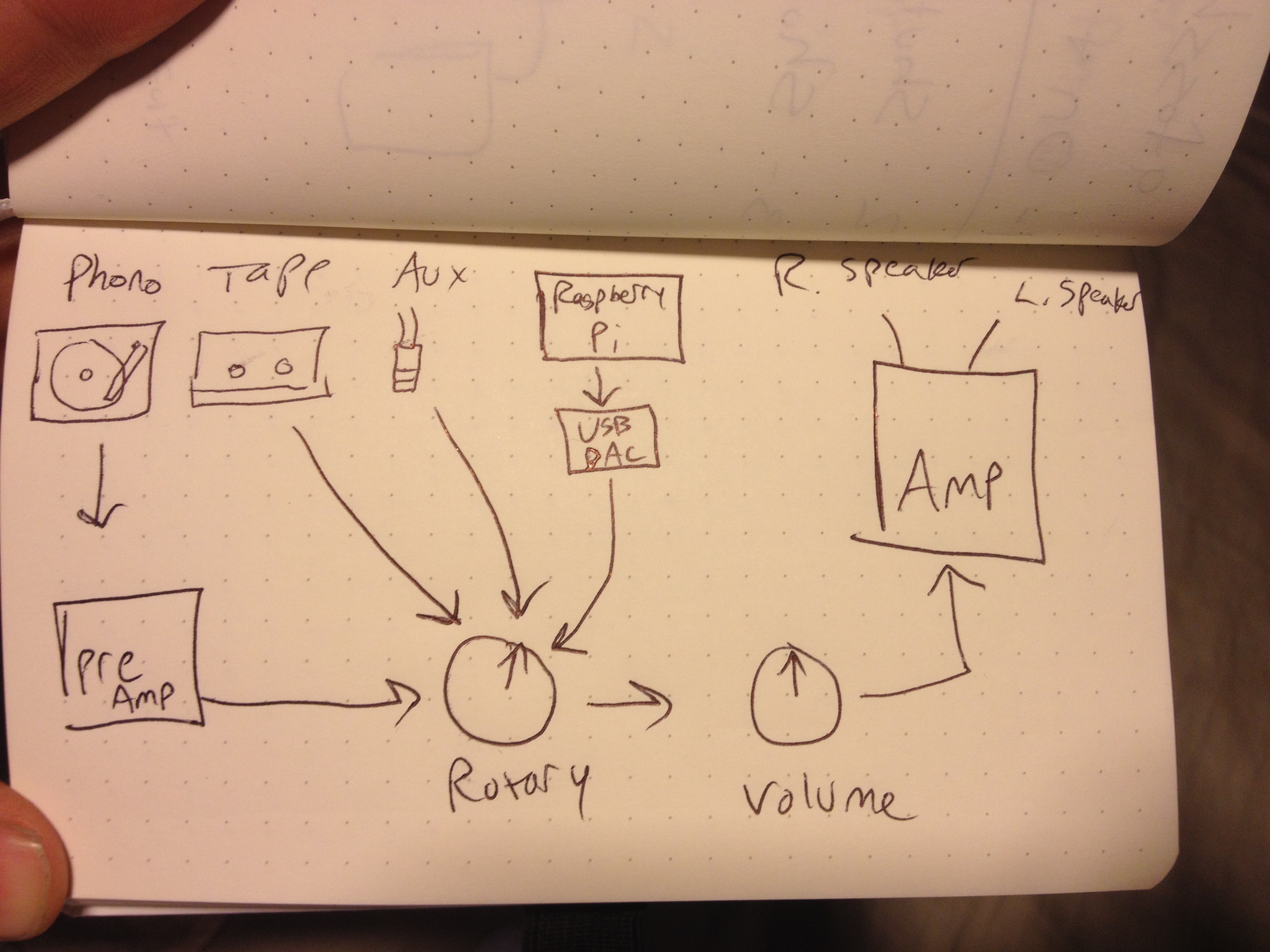
I knew the stereo had to have at least three inputs: phono, tape, and auxiliary (a headphone jack for random iPods or computers). However, I had been experimenting with Raspberry Pi and I read about an option to use it as a wireless Airplay receiver using the Shairport program. All four inputs could be routed to the amplifier using a four-way rotary switch (with two common pins- one for the left channel and one for the right).

Building an amplifier from scratch requires some higher level audio engineering, so I decided to buy one pre-fabricated. The amplifier I selected was also from Parts Express, but this time I selected a Class-D board that puts out 100 watts per channel. This matches our speakers and will optimize the sound quality. The only problem is that it lacked a gain (volume) knob.
To solve this problem, I put a dual potentiometer in between the rotary and the amp to control the volume of both left and right channels simultaneously. I found that a 10K logarithmic pot had the best taper for volume control.
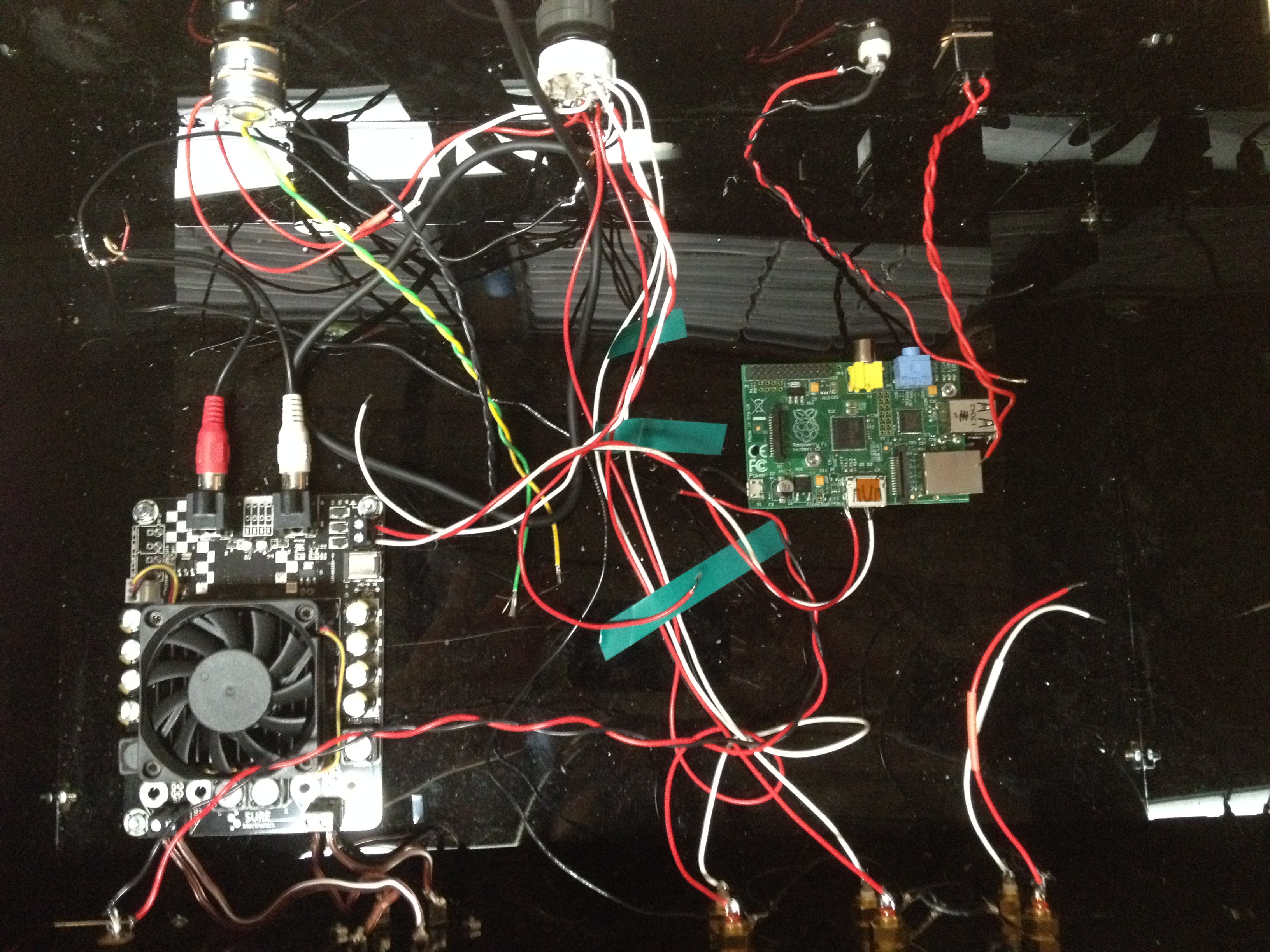
The Raspberry Pi was working pretty well as the AirPlay device, but the digital-to-analog converter (DAC) was not the best for audio, so I bought a USB DAC on eBay and routed the audio out of the USB port instead of the audio jack.

I had previously constructed a preamp kit made by Velleman and used it with my record player. It used the TL072 op-amp, and the sound quality was pretty good. I did a bit of research into op-amps and decided to upgrade to the NE5532, which is optimized for audio applications. I could have just purchased this kit again, but since I needed a few more connections, I decided to create a board in Eagle and have it fabricated.

In addition to the phono preamp, I needed to mount headers for the Raspberry Pi (for power), a place for the on/off switch, power LED, and a regulator to change the 24 Volts (necessary for the amp and preamp) down to 5 volts (for the Raspberry Pi). For this I chose a switching regulator on DigiKey that was rated for 24 volts. This should keep heat dissipation low and prevent anything from getting too hot.
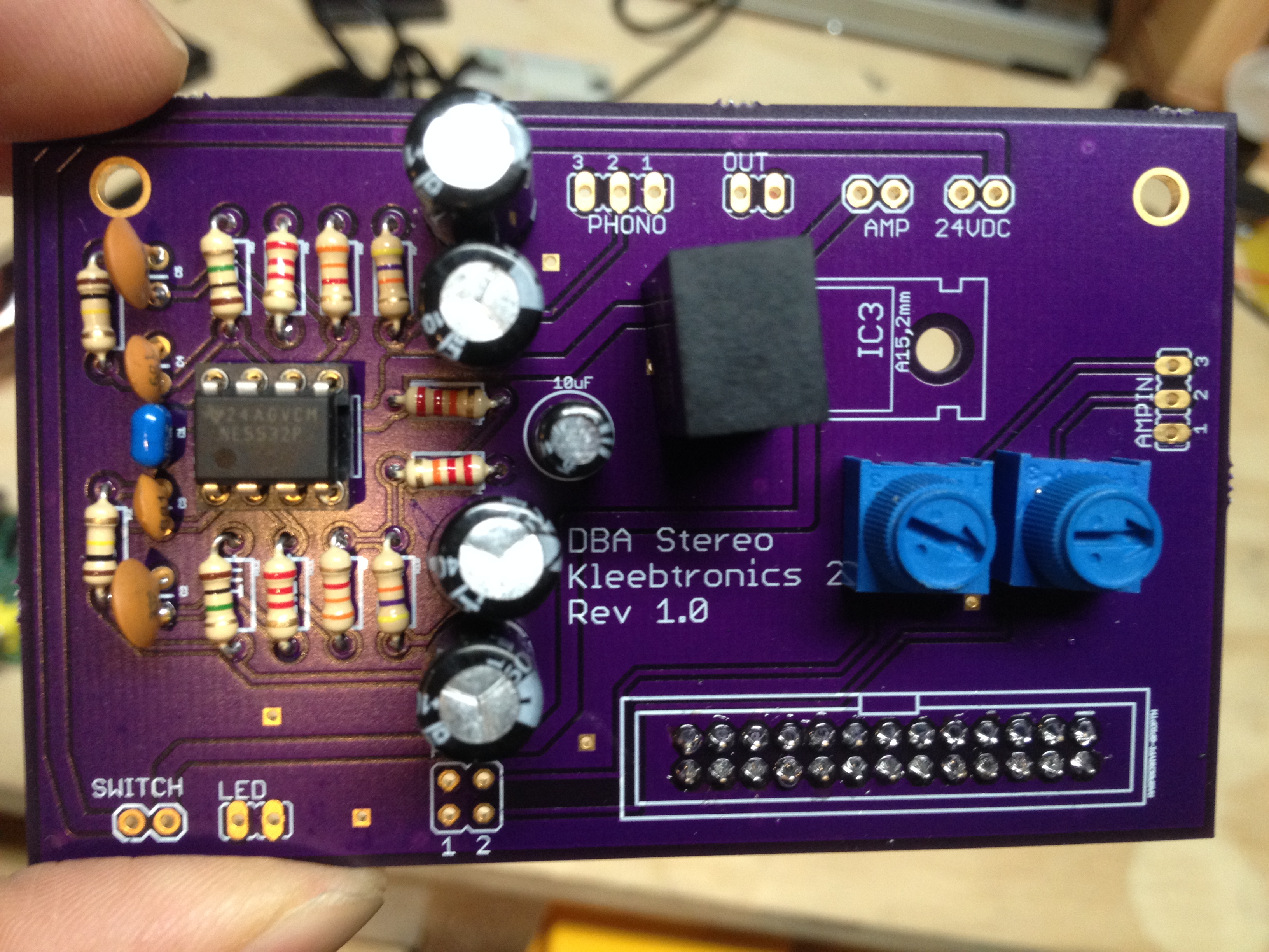
I also decided to add two trim pots for each channel in between the external volume pot and the amp, so that I could set the max volume internally.

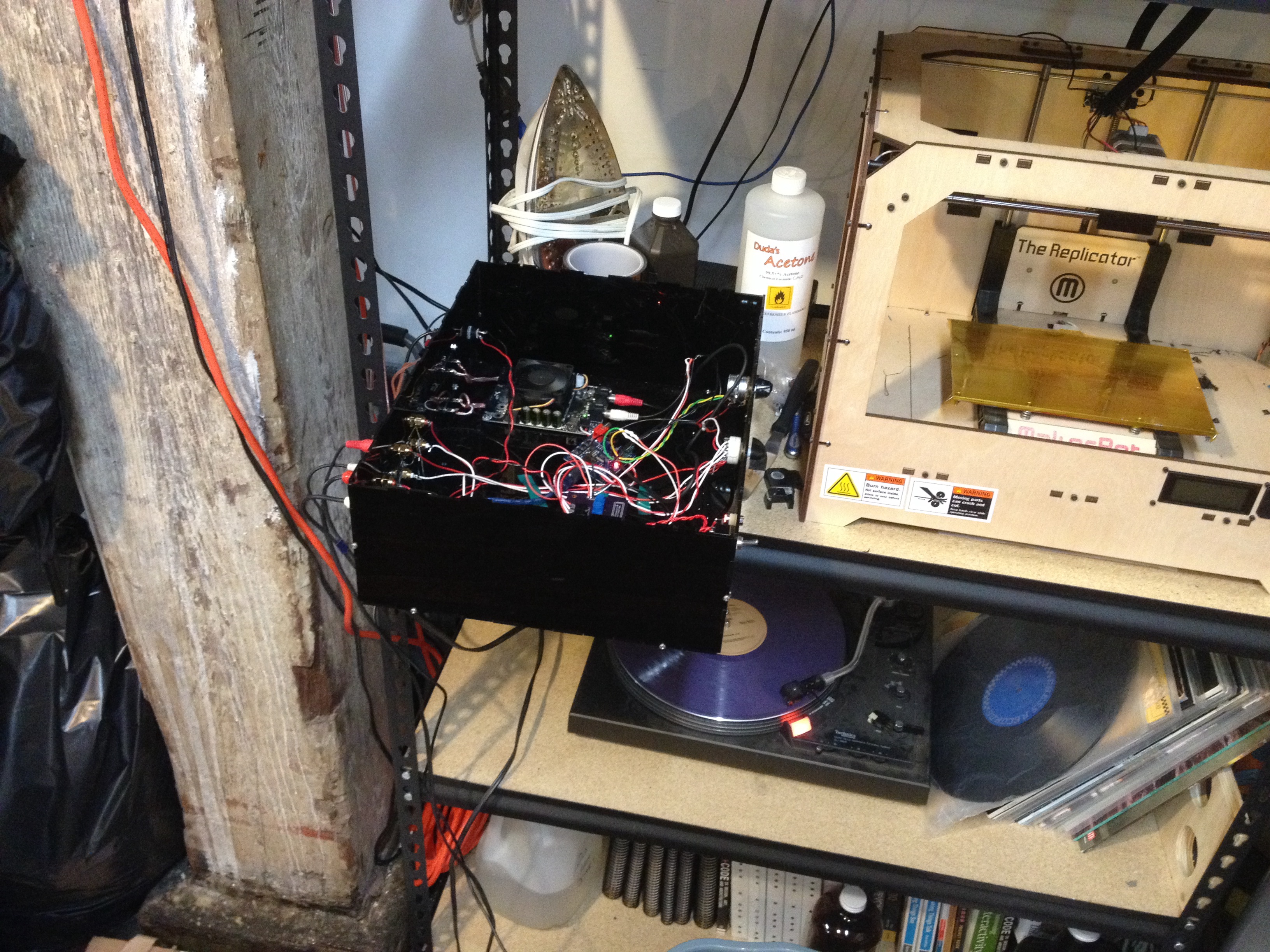
The enclosure was made on a laser cutter using 1/8" acrylic. I used MakerCase to get the right box dimensions, and chose T-slot connectors so that I could screw everything together with machine screws. This was also super convenient because I was able to cut holes for all of the parts with the laser rather than drill through the delicate acrylic.
One lesson I learned is that a Raspberry Pi shield should be wary of any connections that lie directly above the USB and Ethernet ports, as they will short these. I couldn't figure out why my preamp sounded so horrible until I covered these with electrical tape.
Now our audio setup is complete.
The Raspberry Pi required me to pre-program the wi-fi network and password so it could automatically connect via USB wifi. However, if I wanted to sell this as a product, I would need a way for the Pi to connect to any network. I think having an Ethernet port on the back and hard-wiring the stereo to the network is the best bet, but also a pain to add another wire.
Ideally, I'd also like to design my own amplifier and build this into the circuit board. I'm going to have to learn a bit more about amp building before I can attempt to pull this off.