
For one of my first projects of 2014, I'm optimizing a circuit that produces an analog square wave based on the envelope from a piezo transducer. In short: a drum trigger. I wanted this circuit to be as simple as possible, and it required at least three components: the voltage controlled oscillator (VCO), the Piezo envelope, and a voltage controlled amplifier (VCA).
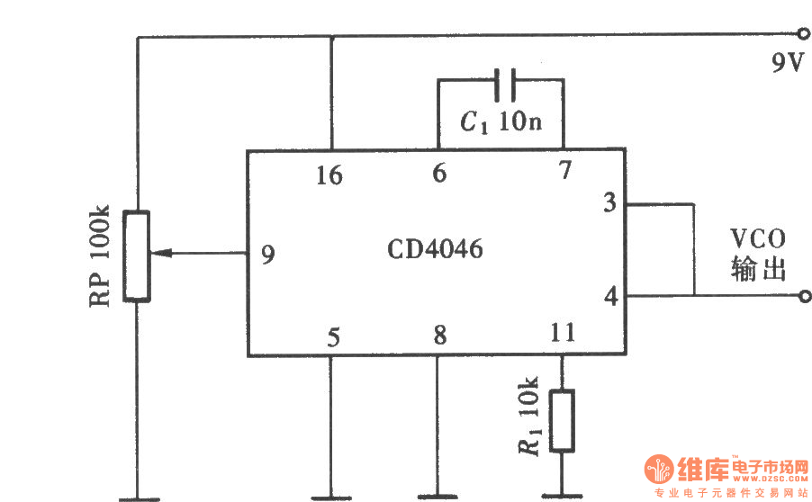
I started with the VCO, since I had built a few of these before. I decided to go with the CD4046 PLL circuit, as it only requires two resistors and a capacitor. This is the same circuit I used in our analog sequencer, so I knew it was dependable. A 10K pot is used on Pin 9 to adjust the input voltage.
This isn't the only VCO circuit out there. There are some that utilize the CD40106 Hex Inverter chip, as well as a 555 astable multivibrator. Beavis Audio has some great examples of hex inverter oscillators.

The most difficult part of this circuit is translating the voltage spike from the piezo into an audio envelope. Here, I referred to Ray Wilson's Drum Synth circuit, and used the TL072 op amp to produce a Control Voltage (CV) from the piezo hit. I didn't need the Trigger portion of the circuit, so I only used one chip to produce the CV output. This circuit also seems to work great with other op amps, like the NE5532 and the LM358.
One big issue with this circuit is that it requires +/- 9 volts, which requires two 9V batteries. This can be accomplished by attaching the - of battery 1 and the + of battery 2 to ground, then routing the remaining wires to +9V and -9V, respectively. Ideally, I'd like to build this circuit with one battery, and am currently researching ways to reduce the required voltage.
The VCA of this circuit is necessary to amplify the volume ONLY when the piezo is struck. This produces a decay that corresponds directly to the voltage of the piezo. To do this, I researched simple VCAs and came across a single transistor VCA that uses a 2N3904 NPN transistor to gate the two signals. The optimal capacitors for this circut seem to be around 0.1 uF, but changing these will alter the decay time. R1 is 100k and R2 is 33k for this particular build.

This is the first prototype of the circuit. The input voltage varies, so I've been adjusting the input resistors (3x 1M-ohm) to find the right threshold for the piezo. The range of the pot for the CD4046 is also not ideal, so I may look into alternatives for the VCO moving forward.